Radar Types and Components


Some of the following material is taken from Radar for Meteorologists, 3rd Ed., by Ronald E. Rinehart, Rinehart Publications, and some from the National Weather Service JetStream Online School for Weather--Radar FAQ, some from WW2010 Online Remote Sensing Guide, and some other online sources.

All radars include at least the following four components:

    (1) transmitter to generate the high frequency signal
    (2) antenna to send out the signal and to receive echoes back
    (3) a receiver to detect and amplify the signal
    (4) a display system

Radar Types

Early radars used a transmitter that generated a signal continuously and had separate antennas for transmitting and receiving, often at some distance apart.

Most current weather radars send radiation in pulses rather than continuously, and have a single antenna for both transmitting and receiving.

There are several different ways to classify radars including hardware configuration, functionality, and wavelength. Some examples of these (sometimes overlapping) categories of radar are listed below; each category of radar has its advantages and disadvantages, which dictate what its final use is:

    (1) monostatic--single antenna for both transmitting and receiving. Ex.: weather radar.

    (2) bistatic--two separate antennas, one for transmitting, one for receiving. Ex.: military over-the-horizon radars.

    (3) continuous wave (CW)--electromagnetic radiation is sent out continuously. Ex.: police radars for catching speeders.

    (4) pulsed wave--the radar sends out a very brief pulse of EM energy, then spends a much longer time "listening" for return echoes. Ex.: weather radar.

    (5) Doppler--can detect target motions by measuring small frequency changes from the emitted to the returned EM pulse.  The frequency changes are due to the Doppler effect of movement of the target in the radial direction, i.e. toward or away from the radar.  This causes a shift toward longer wavelengths (lower frequencies, "red shift") for objects moving away from the radar, and a shift toward shorter wavelengths (higher frequencies, "blue shift") for objects moving toward the radar. Ex.: Police radars and the NEXRAD weather radars have Doppler capabilities.

Several different categories of weather radars include

    (1) terminal doppler weather radar (TDWR)--system sposored by the FAA as an addition to the NWS NEXRAD radars. Their main purpose is to detect low-level wind shear at airports.

    (2) airborne weather radar--these radars have a small-enough antenna to be mounted on airplanes; therefore they run at a shorter wavelength (
higher frequency--most are X-band radars at a wavelength around 3 cm [see table of bands below]) than the longer wavelength land-based weather radars whose antenna must be much larger to achieve the same angular resolution (for example, NEXRAD is an S-band radar with wavelength 10 cm).  Short wavelength signals are more attenuated (weakened) than longer-wavelength signals, so the airborne radar range is shorter than their ground-based weather radar counterparts.

    (3) C- or X-band radars used at television stations and small airports

    (4) S-band radars such as NEXRAD also known as WSR-88D.

The following is a list of the different wavelength classifications of radar( source: https://www.newworldencyclopedia.org/entry/Radar):

Band Name Frequency Range Wavelength Range Notes
HF 3-30 MHz 10-100 m coastal radar systems, over-the-horizon (OTH) radars; 'high frequency'
P < 300 MHz 1 m+ 'P' for 'previous', applied retrospectively to early radar systems
VHF 50-330 MHz 0.9-6 m very long range, ground penetrating; 'very high frequency'
UHF 300-1000 MHz 0.3-1 m very long range (e.g. ballistic missile early warning), ground penetrating, foliage penetrating; 'ultra high frequency'
L 1-2 GHz 15-30 cm long range air traffic control and surveillance; 'L' for 'long'
S 2-4 GHz 7.5-15 cm terminal air traffic control, long range weather, marine radar; 'S' for 'short'
C 4-8 GHz 3.75-7.5 cm Satellite transponders; a compromise (hence 'C') between X and S bands; weather
X 8-12 GHz 2.5-3.75 cm missile guidance, marine radar, weather, medium-resolution mapping and ground surveillance; in the USA the narrow range 10.525 GHz ±25 MHz is used for airport radar. Named X band because the frequency was a secret during WW2.
Ku 12-18 GHz 1.67-2.5 cm high-resolution mapping, satellite altimetry; frequency just under K band (hence 'u')
K 18-27 GHz 1.11-1.67 cm from German kurz, meaning 'short'; limited use due to absorption by water vapor, so Ku and Ka were used instead for surveillance. K-band is used for detecting clouds by meteorologists, and by police for detecting speeding motorists. K-band radar guns operate at 24.150 ± 0.100 GHz.
Ka 27-40 GHz 0.75-1.11 cm mapping, short range, airport surveillance; frequency just above K band (hence 'a') Photo radar, used to trigger cameras which take pictures of license plates of cars running red lights, operates at 34.300 ± 0.100 GHz.
mm 40-300 GHz 7.5 mm - 1 mm millimeter band, subdivided as below. The letter designators appear to be random, and the frequency ranges dependent on waveguide size. Multiple letters are assigned to these bands by different groups. These are from Baytron, a now defunct company that made test equipment.
Q 40-60 GHz 7.5 mm - 5 mm Used for military communication.
V 50-75 GHz 6.0 - 4 mm Very strongly absorbed by the atmosphere.
E 60-90 GHz 6.0 - 3.33 mm
W 75-110 GHz 2.7 - 4.0 mm used as a visual sensor for experimental autonomous vehicles, high-resolution meteorological observation, and imaging.

Additional description of radar wavelength bands pertaining to weather radar can be found here.

How Weather Radar Works Using NEXRAD as an Example

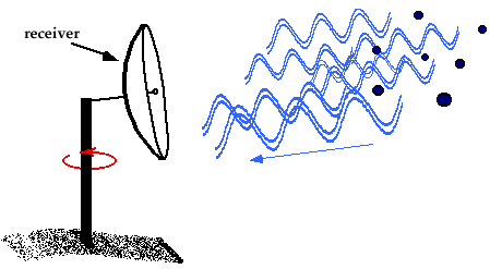
Weather radars are active remote sensing instruments meaning they send out pulses of electromagnetic (EM) radiation which then bounce back as "echoes" from targets suspended in the air.  The meteorological targets of weather radar are precipitation areas, although frequently other features such as insects and birds may be seen.


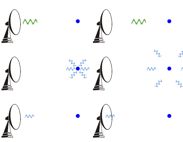
When weather radars sense precipitation, they are not measuring returns from just one single target, but from a whole ensemble of targets, i.e., the individual echoes from millions of raindrops:


The radar scans 360 degrees around the horizon sending out pulses and measuring the amount of power returned from the environment.  With each pulse, the radar samples successive volumes of atmosphere along the beam, called range bins (range is the distance from the radar to the targets).

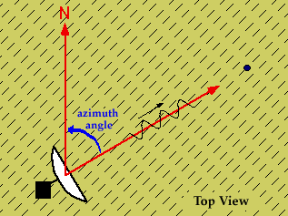
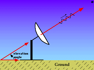
The radar gathers three pieces of information to locate the source of the returned power (usually, but not always,  precipitation!):

Azimuth angle:  Angle of the beam with respect to north, moving clockwise around the horizon.


Elevation angle: Angle with respect to the ground.


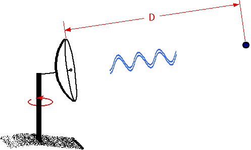
Distance: Distance to the target given by

D = (c xT)/2

where c is the speed of electromagnetic radiation, T is the elapsed time since the pulse was sent out, and D is the distance to the target (range).


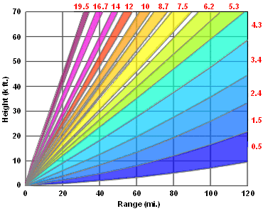
With NEXRAD, once the radar has completed one or two scans at one elevation angle, then it steps up to the next elevation angle and performs another 360 degree scan; NEXRAD uses a variety of different combinations of elevation angle and scanning speed to cover a volume of atmsosphere defined by the specific volume coverage pattern (VCP--more on this later).


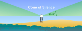
The NEXRAD antenna cannot point higher than 19.5 degrees above the horizon, so there is a volume above the radar that never gets scanned, called the "cone of silence."


Weather Radar Components

Transmitter

Two important advances in the development of radar occurred in 1939: (1) the invention of the magnetron, a type of transmitter that allowed for radars to operate at higher microwave, instead of radio frequencies, with greater power output. 
This enabled the use smaller antennas which allowed the radar to determine direction to a target more accurately. (2) The klystron, a type of transmitter which can strongly amplify a signal.

Magnetrons are so effective at what they do that they are still used in microwave ovens, for example.  In fact, the microwave oven was a spinoff of radar, invented by Dr. Percy Spencer, who noticed that a candy bar he had in his pocket melted after he was working with a magnetron.  The first commercially produced microwave oven was called the Radarange by Amana, released in 1967.

The advantage of a klystron over a magnetron is that it coherently amplifies a reference signal so its output can be precisely controlled in amplitude, frequency, and phase.  This is a crucial element for a doppler radar.

Klystrons are used in the National Weather Service's NEXRAD doppler radar system because of the above-mentioned properties.

Modulator

Switches transmitter on and off to provide correct waveform for transmitted pulse.  Performs timing and duration of transmission.

Master Clock/Computer

The computer controls most components of radar operation, and also serves to process the received data.

Controls how often and how long transmitter transmits.  This rate is called PRF Pulse Repetition Frequency measured in cycles/sec or hertz (Hz).  PRFs may range from 200 to 3000 Hz.

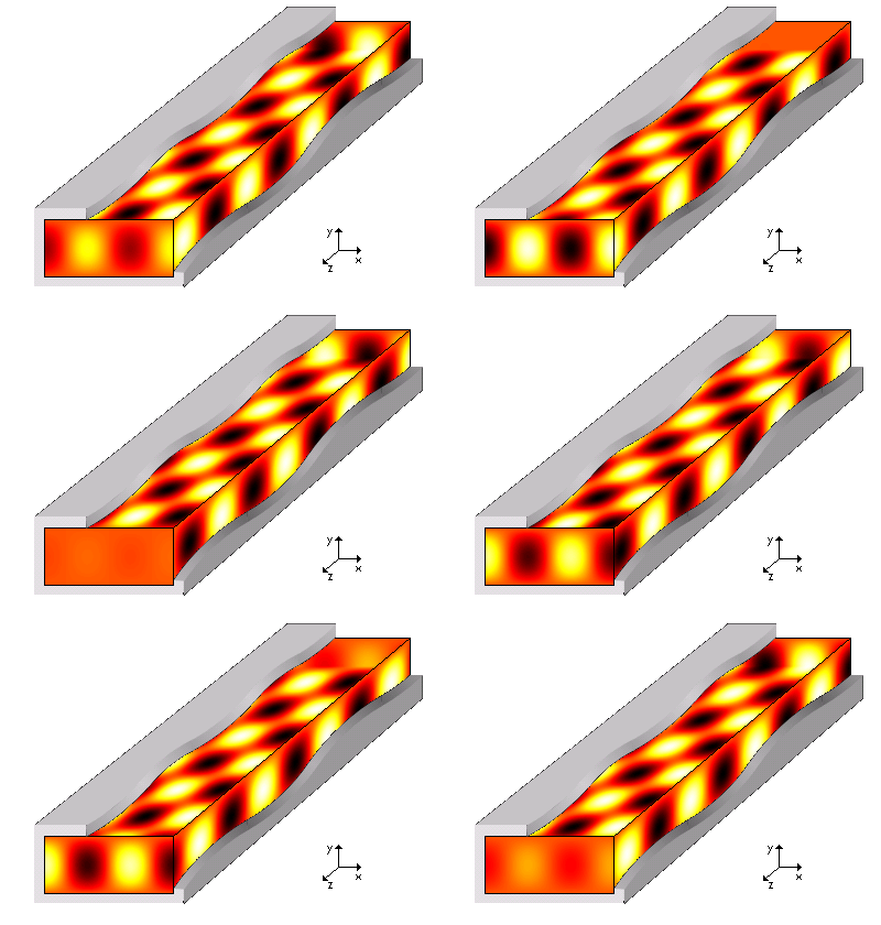
Waveguide

At microwave frequencies, wires lose too much signal, so the conductor that connects the transmitter and the antenna is called a waveguide.

It is a hollow rectangular metal conductor connected by special joints to reach from the transmitter/receiver area, all the way to the antenna which is mounted on a tower.


Antenna

Most radar antennas are directional; they aim energy in one direction like a flashlight.

An isotropic antenna is one that sends energy in all directions equally, kind of like light from a candle.

Antenna gain is its ability to focus the antenna energy into a narrow beam.  It is the ratio of the power received at a specific point on the beam axis to that which would be received at the same location from an isotropic antenna.  The higher the gain the more focused the beam is.

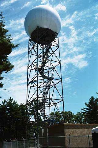
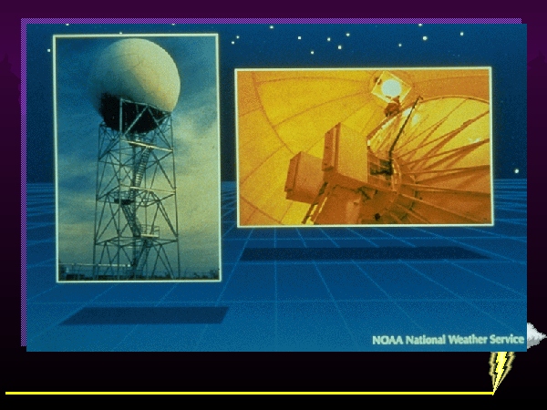
The following images depict a NEXRAD radar antenna enclosure and the antenna itself:


Display

Two main types:

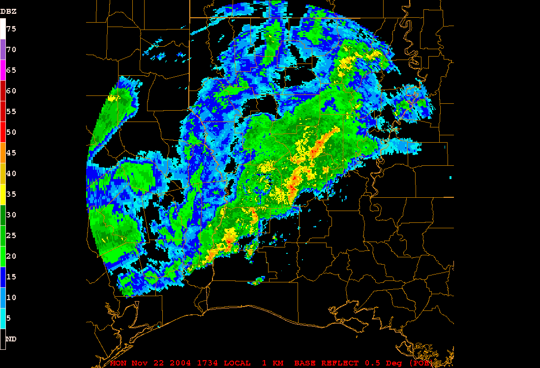
(1) PPI--plan position indicator--gives a weather map view of the radar echoes, i.e. 2-d horizontal:


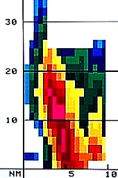
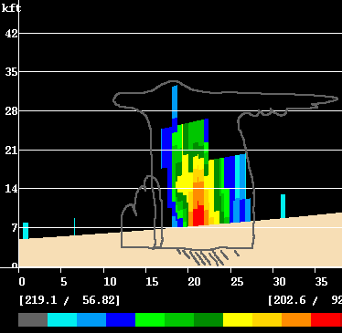
(2) RHI-- Range height indicator--gives a vertical cross section of radar echoes, i.e., 2-d vertical. The following image shows an RHI depiction of a hailstorm from NWS Louisville, KY; note the tilt of the updraft (an important ingredient for severe thunderstorms) and the intense echoes suspended above 10,000 ft:


The next image from Roland Stull at University of British Columbia shows an RHI of thunderstorm reflectivities with the outline of the thunderstorm superimposed: